
T: +86-139-5050-9685
E: sales@bycpower.com
E: sales@bycpower.com
No. 13, Jincheng road, Tiehu village, Chengyang town, Fuan city, Fujian, China


Views: 0 Author: Site Editor Publish Time: 2026-07-08 Origin: Site


Erratic voltage or total power loss in critical infrastructure often points directly to the AC alternator or its excitation system. Power instability compromises operational safety. It also halts operations immediately. You simply cannot afford prolonged diagnostic guesswork when critical power systems fail.
Misdiagnosing an electrical failure leads to unnecessary component swapping, extended downtime, and wasted maintenance budgets. Maintenance teams sometimes assume the control board has failed without properly testing primary windings. You need a systematic approach to pinpoint exactly where the fault lies before tearing down heavy machinery. Identifying the true root cause ultimately saves valuable diagnostic labor hours.
We provide an evidence-based diagnostic framework to isolate faults between the stator, rotor, and AVR. You will discover clear criteria for deciding whether to repair or replace the entire unit. By applying these methods, you establish reliable baseline expectations for an AC brushless alternator in demanding applications.
Quickly isolating whether a failure originates from the prime mover or the AC alternator stands as the primary success criterion. Efficient isolation minimizes diagnostic labor hours. It prevents technicians from chasing phantom electrical issues when the actual fault lies within the fuel delivery system.
Accurate symptom mapping guides your next steps. You must categorize the failure immediately. Observe the machine under no-load and load conditions to gather accurate baseline data.
Do not assume a burned-out Automatic Voltage Regulator serves as the true root cause. Technicians frequently replace a visibly damaged AVR, only to watch the new unit fail upon startup. Often, an overloaded brushless alternator causes the AVR to overwork and eventually burn out. Environmental contamination, such as heavy dust or moisture ingress, also acts as a primary catalyst. Treat a failed AVR as a secondary symptom until you thoroughly evaluate the main windings and exciter stator.
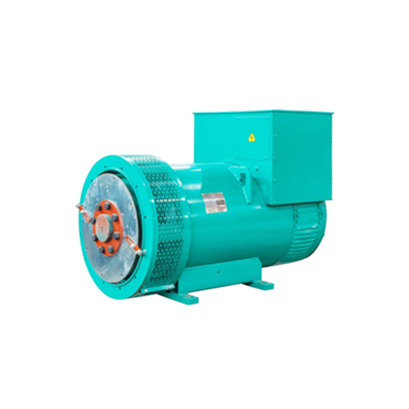
Establishing baseline operational data requires conducting standard multimeter tests safely. Technical verification removes guesswork. Ensure you wear appropriate personal protective equipment. You must also use a multimeter rated appropriately for industrial power environments.
You must measure the output without the AVR connected to the circuit. Removing the regulator isolates the machine's inherent magnetic capability. Start the engine and run it at nominal speed.
A healthy unit typically shows 5–15V (AC) of residual voltage across the main output terminals. This small voltage proves the rotor retains enough magnetism to initiate the excitation process.
Implementation Reality: If residual voltage reads exactly zero, field flashing may be required before further diagnostics can proceed. A complete loss of magnetism prevents the machine from building any voltage, rendering further tests inconclusive until you restore the magnetic field.
Measure the main output terminals across all phases. You will measure L1 to L2, L2 to L3, and L3 to L1. Record these numbers meticulously.
Trustworthiness Note: Readings must be balanced within 1-2%. Significant variance definitively indicates stator turn-to-turn shorts or grounding issues. For example, if L1-L2 reads 480V, L2-L3 reads 478V, but L3-L1 reads 410V, you face a major internal failure. This severe imbalance immediately rules out simple AVR fixes. You must inspect the main stator for burned coils or degraded insulation.
| Diagnostic Test | Expected Healthy Result | Indicated Failure (If Abnormal) |
|---|---|---|
| Residual Voltage Check | 5 - 15V AC | Loss of residual magnetism, broken exciter wire |
| Phase-to-Phase Balance | Values within 1-2% variance | Stator winding short, internal grounding fault |
| Frequency Stability | Steady 50Hz or 60Hz | Prime mover / engine governor failure |
Evaluating the AVR alternator control loop requires isolating components systematically. The AVR constantly monitors output and adjusts the DC current sent to the exciter field. When this loop breaks, voltage regulation fails entirely.
Before connecting any meters, power down the equipment and perform a rigorous visual inspection. Check the AVR board for ruptured capacitors. Look closely for burnt resistors or discolored circuit traces. Pay special attention to melted potting compound. Excessive heat causes the protective resin to soften or leak, strongly indicating a severe thermal overload event.
This procedure remains the definitive method for isolating the automatic voltage regulator from the rest of the machine.
Evidence-Oriented Outcome: If the main output voltage rises smoothly and balances across all phases, the main alternator is fundamentally healthy. This confirms the machine can generate power when supplied with adequate excitation. Consequently, the AVR is definitively the failed component and requires immediate replacement.
Most modern AVR units feature resin-sealed (potted) construction. Manufacturers use this dense potting compound to protect fragile surface-mount components against severe vibration and moisture ingress. Because of this heavy encapsulation, component-level repair is rarely viable. Attempting to dig out a burnt resistor damages adjacent microchips. Swapping the failed board with a known-good OEM equivalent remains the accepted industry standard for minimizing costly downtime.
Once you identify a catastrophic failure in the main windings, you face a critical operational crossroads. Core winding failures demand strict analysis between rewinding the existing unit or sourcing a completely new assembly.
Calculate the total repair estimate comprehensively. You must include stator rewinding, rotor dynamic balancing, dipping, baking, and mandatory bearing replacement. If these combined expenses approach 60% of the cost of a brand-new generator alternator, replacement becomes economically superior. Investing heavily in old iron rarely yields a positive return once you surpass this specific financial threshold.
Time frequently dictates the final decision. Compare your local rewind shop turnaround times against the immediate availability of a drop-in replacement. Rewind shops often require two to four weeks for a complete teardown, rewind, varnish, and cure process. If your facility loses thousands of dollars per day during an outage, downtime costs rapidly outweigh any minor savings gained from repairing the old unit.
Rewound alternators often carry shorter, limited warranties. A typical repair warranty might cover craftsmanship for three to six months. Conversely, new OEM units generally arrive with robust 12-to-24-month warranties. Choosing a new unit mitigates future operational risk significantly.
Use the failure event as an opportunity to evaluate current power demands. Facilities frequently expand over time, adding heavier motor loads or new production lines. Evaluate if the current facility load has outgrown the existing kVA rating. A burnt stator often signifies chronic overloading. Replacing the failed machine provides an excellent opportunity to right-size the power system for future growth.
| Factor | Repair (Rewind) | Replace (New Unit) |
|---|---|---|
| Initial Cost | Typically lower (unless damage is severe) | Higher upfront capital expense |
| Turnaround Time | 2 to 4 weeks (high downtime) | Immediate (if local stock is available) |
| Warranty Coverage | Limited (3-6 months generally) | Comprehensive (12-24 months) |
| Capacity Upgrade | Impossible (fixed to original spec) | Possible (can right-size kVA) |
Specifying a replacement unit requires strict attention to detail. You must match parameters perfectly to ensure flawless system compatibility. Guessing dimensions or electrical specifications leads to disastrous installation delays.
Mechanical fitment stands as your first hurdle. You must verify the SAE housing and flywheel dimensions carefully. Measure the pilot bore diameter and the bolt circle precisely. Confirm the shaft height from the mounting feet to the centerline. Finally, identify the specific coupling types used between the engine and the alternator. A mismatch of even a few millimeters prevents successful mating.
Electrical specifications demand identical rigor. Match the kVA and kW ratings. Confirm the exact output voltage and operating phase configuration. Verify the power factor rating, which usually stands at 0.8 for industrial machines. Furthermore, ensure the new automatic voltage regulator supports existing parallel operation requirements. If your system utilizes grid-tie synchronization, the replacement control board must accommodate external voltage trimming signals.
Operating environments destroy unprotected equipment quickly. Select appropriate Ingress Protection (IP) ratings based on location. Standard IP23 enclosures work fine in clean, indoor generator rooms. However, if the industrial power alternator operates outdoors, near coastal areas, or in particulate-heavy environments, you need IP44 or higher. Additionally, specify anti-condensation heaters to prevent moisture buildup inside the windings during extended shutdown periods.
Do not rely on memory when requesting a quote. Compile all original nameplate data. Take clear photographs of the identification tags on both the engine and the alternator. Gather your recent load profile history. Measure the physical dimensional constraints inside your canopy or generator room. Present this comprehensive data package to an engineering sales team for a definitive, accurate replacement quote.
A: By disconnecting the AVR and applying a fused 12V DC battery source to the exciter leads to measure main stator output (the "12V battery test").
A: Prolonged periods of inactivity, severe short circuits, or running the generator under heavy load while shutting it down.
A: While possible for basic standby units, mission-critical industrial applications require exact OEM matches to ensure correct voltage regulation curves, surge handling, and warranty compliance.


